

Das QTH ist JN77QC in Gösting, Graz, Österreich. Ich war einmal Entwickler für Optik und Elektronik, dazu kann ich in meiner kleinen Bier Brauerei ein gutes QKB machen die Stammwürze ist 14% bis 17% mit einen Alkoholgehalt von 7% bis 9% die Farbe ist von blond bis hin zu schwarz und es werden 80 bis 120 Liter gutes und echtes Bier das nicht lügt per Durchlauf gemacht.
Svenska är mitt modersmål men det använder jag bara när släkten är på besök, resten av min sida håller jag på engelska eftersom det mesta är av tekniskt natur. Du som har hamnat vilse på min sida kan jag bara gratulera och önska dig en trevlig älg och hare bra.
My rigs are:
1. Yaesu 857D and an auto tuner, plus lots of ad on for it
2. Two Yaesu FT60 one wouxun KG-UV8Q two well working Sommerkamp FT250 and one big manual tuner.
3. One Adalm Pluto and lots of amplifiers for it, several 2.4GHz 230W PAs several 435MHz 270W PAs one 145MHz 600W PA, one HF 600W PA.
The PAs are not ready for antennas yet as proper water cooler and filters and circulators and sequencers and lNAs has to be added.
The koax Relais are in the junk box.
4. A lot of SDR toys like Malachite and SDRplay. Front end narrowband filters, laptops and palmtops and a bunch of arduinos and raspberries.
5. More SW and FW then I need.
6. Enough tools
7. Too many ideas
8. Use this link for ideas and parts and components. https://www.w6pql.com/
9. If you need a bucket full f ideas just use this link
10. The latest gadgets are a uSDX QRP 8 band transceiver with its ATU, portable antenna and power battery bank.
Ailunce HS2
My experiences
I bought this all band all mode QRP transceiver from Ailunce in China for 659€ inclusive all. To make a very long story a bit shorter I must say I will not do this again and I would recommend you to avoid this product.
The company Ailunce has no customer service or support worth the name. Their lack of skills in linguistics and technics is embarrassing.
I got this unit about one month after order with some issues concerning the tracking number, it finally arrived safely by DHL. I payed with PayPal to assure my money refund in case of a screw up. After unboxing I connected the unit to my measurement system and started to check through all settings, it was not too bad but some issues occurred and I reported those to Ailunce, the reply was in the range of “yes we have no bananas”. After two weeks of annoying communication with a stupid, ignorant bitch I finally got some useful feedback.The major issue was that it was too far out of frequency, about 2.5kHz on the 70cm band.
This is not acceptable, their spec claims a 0.5ppm TCXO, I suppose this is the stability and not the accuracy. I needed to search the internet to find a way to correct this. Ailunce support was too slow to deliver a proper answer. Thanks to some YouTubers I got this procedure and adjusted the accuracy with my GPSDO to be within 20Hz at 433MHz, the steps are about 20Hz so this was the best figure and I’m ok with that. So far it is stable. It was also a bit hard to find how to write the call sign into the welcome screen, their manual is a bit messy but again YouTube helped

In addition i found some other errors, the power output on the HF bands was not too far of what is acceptable, 20W says the spec. At 160m it was 12W, at 40m it was 26W, at 10m it was 18W. Unfortunately it was only 6W on 6m.
On 2m it was 12W and on 70cm it was crappy 3W spec says 5W. Could have been worse I guess. The out of band transmission is better but close to the required 46bBc on all bands but not even close to what the Ailunce spec claims.
The NFM has a modulation that only has 1kHz deviation, this is useless.
The WFM has 5kHz deviation and sounds just fine. This is 16F3 just right, (5+3)*2=16.
There is an audio compressor setting that is nothing but a place holder, you can manipulate it but it is not changing anything with any modulation type what so ever, fake.
The power output setting is not linear and has different linearity for all bands, you must calibrate and learn its behaviour with an external reliable instrument. The built in antenna tuner works fast but has a limited range of about Z=13—-200 Ohm, (SWR <1:4)
Some notes
There are a few PINs
Factory pin 200510
Agent pin 685911
User pin 000000 (no use so far)
Turn on the TC, long press the MENU key, enter SET, select #0 key led,
Long press the PA button,
Now put your desired pin into the password position (685911),
Reached “agent setup”? If ok then long press the MENU key,
Now long press the #9 key,
You will now be able to enter:
Tx offset (+61)
S meter (+25)
Delta VDC (+43) By the way, this unit runs from 7VDC to 32VDC
RC offset (-61) Peculiarity ?
In Factory pin mode you must be careful to change only what you for sure know is correct to change or you might end up with a brick.
It’s your station, and it’s you risk. If you screw it up don’t expect to get help, unless you have the powers to threaten those rice shitters with a nuke

Final lyrics
So, is it useful? Yes, the transceiver works quite well, and one can hope that Ailunce will improve their major issues with poor FW design and close to zero customer support.
There is an embarrassing issue concerning the power output Indikator,
When transmitting at HF the output power reaches 20W but the scale only goes to 5W so there is allways an overflow unless you reduce the power to under 5W, this is stupid, right?
On VHF/UHF the power output is 5W and the indicator scale now goes to 20W, crazy, those idiots got it the wrong way around. I rather would like to have the same scale for the power indicator on All frequencies, but as a logarithmic presentation, if <1W then =0, if 1W or more, then a log presentation up to 30W.
0-1——3——10——30
The feedback I gave was clear but Ailunce doesn’t understand or they don’t want to understand. The FW i have is 3.1.1 and after some frustrating communication with a Chinese bitch I got a FW 3.1.4 to test.
This was twice the size of 3.1.1 and full of bugs, it was like an anthill with a foot into it. Nothing was to the better, everything was a major fuck up.
By the way, the Bluetooth app for Android works only on a few android Phones, don’t count on a proper function, I contacted the app designer and he claims that his app is not developed for HS2, he also claims he is too busy to debug it, I told him that he is a lazy idiot that should get nuked. The BLE app works on iOS, iPad with some stability Problems.
This product has been on the market for a few years now and I did expect a bit more professionally behaviours from the marketing, design, quality assurance and so on from this bloody Ailunce company.
I suppose it was a concept to copy the ICom705 concept and push it onto the market really fast. And fast it was but what it ended up with was a Chinese slut in customer support, an idiot FW designer and a few kids that do the final assembly and packaging, no calibration or testing or whatsoever

Some notes
It is nice that the unit goes from 7 to 32 VDC but it is also crappy that the unit can require up to 66W of power, it is depending on a lot of parameters and I am using dc power meter to check where the efficiency is appropriate. Also it is to be noted that once you have a setting of your choice, say 10W out on the 40m band, you can vary the voltage from 11 to 14 VDC without a major RF power output change, it stays within 9% or less. The conclusion is that there is an ALC for the RF stage.
In factory mode it is possible to set the max power level for each band.
Also you can update the unit with a GPS, DMR, Compass, and other Gadgets, I have no use for that as it only consumes more power for nothing that I do not have already, plus the Chinese option of a chest full of hot bugs and no support. It’s already bad as it is. And you must pay quite a bit for that crap. Check YouTube and hear all the complains people have, ok some YouTubers are very positive,
but those are bought idiots that need both hands to find their own ass holes.


OE6CCP
I received my first licence in Sweden at the age of 16. My call sign was SM7GDO.
16 years later I quitt this Hobby due to lack of time and energy. All my recourses where focused on my family with 5 children, house, beach house, sailboats, RV and a demanding job. At the age of 71 I have recovered and refocused, I am QRV again.
I do have a few other interests as well, I’m an amateur astronomer, a beer brewer, a hiker, a dog owner and I have a woman that is young, beautiful and intelligent but not blond. I have no QSL cards and I don’t chat or Twitter nor tick-tack-tock. What you see is what you get.
Please ignore eventual spelling errors, I speak Englisch, Swedish and German and some times I get it messed up a bit.
This is not a website about grammatical issues, it’s about hobbies. Stay happy and don’t get fussy about 😷. One of the best doctors I know once said “Der Keim ist nichts, der Nährboden ist alles“, this is essential. In general this means if you try to plant seedlings in poor soil they will die. The seedlings are the corona viruses of the type that comes from pigs and the soil is the genetically implants you received from pork.
So if you are full of manure from pork the seedlings planted inside you will grow rapidly,
Yes it is a matter of diet. What you eat is what you are.
Change your diet and your life.
But only if you like.
Be happy.
Cheers.
Prost.
Skål.
干杯
OEM Consulting
My workshop has what I need concerning optics and electronics, it is still updating.

oe6ccp
optics and electronics is a major part.
Sometimes I have to use my chemlab, this is reflux boiling to investigate some material properties.

90 days on the Schiesslingalm with Aisha and Baldur, my two Magyar Vizslas. Hiking almost every day.
This is the place I met my YL

Hiking to health
it’s a great place on Earth

Right in the middle of the scale is where I am watching in both directions and working with a fraction of it

Oldie

Pipeline

Pipe line

Pipe line

Start here when designing the antenna, it sets the number of elements you need to use for your expected gain

One of my VNWA’s

Needed tool for the VNWA when testing S11 S21, S12 S22

Without a VNWA don’t even try

A bit of adjustment was needed then it was ok

bought cheap, redesign for 50 Ohm

Outside of the cold boom or inside if possible

Proper RF connection needed

This is the proper way

My disc cone Antenna in development, bit by bit

Supervisor or super Vizsla
My 135 to 500 MHz home brew LGPA
This was my first run and they work just fine,
They are optimised for bandwidth and the gain is only 6dBd
the calculators I used are on the web.
Diese Seite is eine Baustelle 🚧
the disc cone antenna has advanced a bit more then on the picture, all the rods and rings are made an the disc is finished, the cone rods and ring are to be mounted and a plexiglass tube must be added between disc and cone for stability. I copied this design from a professional antenna in an EMV laboratory, that one was painted in grey so I might do so as well.
These online calculators are quite good and useful for a lot more then a LGPA, do try them out.
OE6CCP
Log periodic antenna for 2m and 70 cm. This design is described in the link and will be followed to 95%. It needs a bit personalisation to be use portable.
I will make one 9 element beam that is possible to disassemble and if that works as expected I will make additional 3 beams, those 4 beams I will diamond stack. For this type of antenna this has a few advantages. The directivity would be 16dBd on 2m and 18 dBd on 70cm. Portable in a sack full of rods.
I just bought a Retevis RT82 in the hope to hear a bit more traffic on UHF, we’ll this was a disappointment, in Austria there is no active HM Radio, just drinking beer and consuming Schnitzel.

Most of the material in house for 4 antennas to be made 1+3 at a time
Don’t try this without a VNWA

Diamond stacking works great for this kind of antenna.

For this type of antenna it is 👍
OE6CCP
This is a magnetic loop antenna for the 80m band, it is designed in a square number eight shape and the tuning is in the center. The material is a 12m length of 20x2mm Aluminium and there are 3 fixed and one variable capacitors of 100pF that can withstand 6kV and 20A@30MHz. A motor for tuning of the varicap will be added and a electrical position limiter prevents the varicap to get damaged. The feed loop will be at the lower half in the shape of a proper diameter ring to adapt it to the 50 Ohm koax.
I will start with a coupling loop diameter of 75cm, that’s a length of about 236cm.
some reasoning gives me those numbers, I will verify and report later.
VNWA is a must

The major part of the material, the rest is in the pipeline or in the junk box

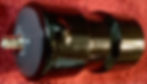
This is the motor, controller, end position switches and potentiometer for the tuning of the vacuum capacitor.
OE6CCP has another project started. It’s a QRP SDR Transceiver and it’s both antennas. Don’t miss the buttons at the end for some *.pdf files.
The antennas are my oe6ccp ODDWEBB antenna that is modular and can be operated in several different shapes. This antenna is resonant on its bands and needs no tuner. It’s range is from 40m to 6m bands. An additional antenna is made, it’s a long wire antenna with a balun and a 1:56 impedance transformer. The balun goes from 100kHz to 100MHz and the transformer works well fron 80m to 10m bands
The TC is a an Arduino based SDR unit, it has a minimum of HW and a clever SW. Essential is that it fulfils the requirements for a QRP station more then well @ a price of under 150€. It’s an open source project under GitHub made in China. The tuner you can get for 80€ plugg and play or 40€ diy. OK! Most of you know about class A, AB, B and C amplifiers, some of you heard about class D amplifiers. Only a few know how a class E amplifier really works. This YouTube channel help you a lot if you are interested to learn.

Life is to short to build an ATU when they practically give them away.
This is an ATU that can handle 160m to 6m bands, the minimum power for tuning is 1W. The maximum power is 100W but I will use it for QRP only. The resolution is 100mW. It has a built in rechargeable battery. Great for end feed Long-wire antennas.


This is the balun and transformer for the long wire antenna.
It is in a plastic box and designed to handle up to 200W from the 80m to to 10m bands. 50 Ohm input and 2800 Ohm output
The antenna is a 21.6m long wire to be launched up into a tree with a fishing line and a slingshot, the counter weight are 3 7m long wires spread on the ground in a star shape. The length 21.6m is chosen to be non resonant from 80m to 10m bands and their multiples.
The upper connector is for the areal part of the antenna and only the outer part of the BNC is used, this is the high impedance output, about 2800Ohm. The bottom connector is the 50Ohm BNC connection to the transceiver. The right hand BNC is the ground connector/ counterweight. This antenna gets an ATU100, It is designed to withstand 150W, although the antenna can handle 200W.
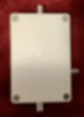
The balun and impedance transformer for the end fed long wire antenna inside an IP66 ABS housing. The wires are free of your choice, try a slinky but do not forget the ground / counterweight, this is important.

The spider in my ODDWEBB
Designed to reach from 40m to 6m without tuning and max 400W. It can be configured for 20, 17, 15, 12m only or you can add 40, 30m and 10, 6m as well. Also you can reconfigure it into a COBWEB or even into a spider beam. Height over ground on a 30mm mast is 4m minimum and 6m optimum. To be noted is that the feed impedance is 12.5Ohm so the transformer plus balun is a bit unusual, I tested it with the VNWA and it has a very wide bandwidth.
In it’s max config it has the 40, 30, 20, 17, 15, 12, 10, 6 m bands at 6m elevation. It can be reduced to 20, 17, 15, 12 m bands on a 4 m mast. It can be reconfigured into a spider beam on one or two bands and of course it can be turned into it’s origin design as a COBWEB antenna. As you can see it needs a few strings for support as those Glas Fiber tubes are only 12 mm in diameter, each of them is 60cm long and I have 50 of those.
My ODDWEBB antenna has a lot of options for its configuration

OE6CCP files *.pdf

Am Kirchberg, 400m elevation, lot of QRN from bad wether surrounding us.

The major difference is that the free height is at least 6m above ground. I calculated the safety distance and for 400W it is 4m, so if you are shorter then 2m you are just fine.

Final version of this concept

New design trial

Air wound is crap, don’t do this

The new balun, about 76uH

Hard to wind without this center bobbin


My magnetic balun in it’s housing ready to play

Top lid for the balun

Coax rolled up on a winder.

28m antenna wire, 13m feed ladder, balun and 20m coax cable on a single cable winder. Easy to handle.

Ground spikes included

The final 10m mast ready to go

The two 6m masts are ready to be raised

Next warrant in the pipeline

Trap design

To be inserted into the housing pipe.

Coaxial cable traps tuned to the proper frequency and fixated with a crimp sleeve
One of two 11uH coils for the 160m band, the traps will lock the same but instead of a black crimp sleeve the colour will change depending on its design frequency.

80m and 40m traps, two of each are made. Black ring towards the center of the dipole

I will try this portable HF antenna made of my 12mm thick Glas Fiber rods as I have 30m of those in my junk box

Tested from 160m to 6m bands to a svr better the 1:1.3 and an attenuation of less then 0.3 dB.

Image from nanoVNA-F wit the 4:1 balun connected to a 12.5 Ohm load, more than good enough.

95% of the parts in house. 50* 600mm GFK tubes interconnected with 16*12mm Alu tubes, clips for the antenna wire, 200*3mm Alu discs and a housing for the balun.

oe6ccp oddwebb balun 50/12.5 Ohm

Balun In the box

My oddwebb configured 20, 17, 15, 12, 10, 6 m bands, easy to backpack

When the 40 and 30m bands are added some support wires must be added as well. The total weight is still manage able.

The spider in my oddwebb antenna, it is now ready to add the antenna wires and tune it.
OE6CCP
This is the multi band antenna project that is well presented in the link below and successfully finished in the first stage of development. the 3 masts are raised and supported with paracord wires, then the antenna wire is raised to the top of the masts with ropes over pulleys. The ladder goes down into the 1:1 balun and the koax to the tuner. I did just finalise it and it worked like plug and play. We made a mini field day to test it, we are OE6NOA, OE6CBX and OE6CCP, it was easy to tune the antenna at the odd bands and on the design bands no tuning was needed. QSO with 100W on 17m, 20m and 40m from midday to late evening all over Europe, central USA, China and Japan, mostly 5 9, in extreme cases 4 0 to 5 9+++. The negative side is that there are a lot of strings and wires, this will be rectified. See later in a few weeks from now and check the pictures. There will be some design changes and experiments, the goal is to create an antenna that is transportable in a car and can be set up with one person to limited hight and two or more persons to full height. All cables and ropes are stored on a cable winder, all tools and grommets in a sack. All SW bands are to be operable and for the harmonic bands no tuner needed. The efficiency must be better then just good. If traps is a must or other tricks are needed it’s OK. I am thinking about a multi band, standing wave, resonant antenna where the 6m band has coaxial stubs to make a 3 element collinear dipole the same for the 10/12m band and the others a bit shortened with traps, for sure the 160m band must be kept with amputated legs. Starting with the 6m band and check how it resonates on other bands. Using cheap TV coax for trial and error. The air balun was tested and performed well from the 80m band to the 10m band but it was useless on the 160m and the 6m bands. A new balun was made out of two stacked ft240-43 cores with six turns of Teflon coax and this worked perfect on all bands with a lot of power capacity. The first multi band antenna is finished and easy to use, I was able to rise it by myself to full height with no problems. On the masts the support wires are stored nicely and on the cable winders the antenna and extension coax are easy to access, also the power management works great. This concept held what it promised. The next stage is the variant with the magnetic balun and the resonant standing wave antennas from 160m to 6m without the use of a tuner on the SSB side of the bands. 160m, 80m, 40m with traps and coil to get the length down a bit. On the other bands separate wires with spreaders and also used as collinear design to get some directivity. This is an antenna that requires quite a lot of space, but due to the fact that it is for transportable use in combination with a car this is of no concern. I will not go backpacking on mountain tops for HF communication. On VHF and UHF I can use lightweight antennas and transceivers, but that is a different story and I’m not there yet.
Starting with some traps;
160m coil 25 turns multi strand 10,8 μH 136Ω 70mm length, this is to shorten the 160m length.
80m trap 3,8MHz 17 turns 421pF 6,68μH 126Ω 46mm length, fine tune by variating the coil length to 75kHz above, it will sink 50kHz when inserted into the housing.
40m trap 7,2MHz 8 turns 201pF 2,44μH 110Ω 22mm length, fine tune as mentioned above to +100kHz higher and check when inside housing if ok.
Coax 25 Ohm 2,5mm Teflon, 204pF/m, fixated with crimp sleeve.
Coil form diameter 32,5mm PVC with housing and end caps, BNC’s and the caps screw locked.
Resonant close above the high end of the band, measured with loose coupling to VNWA.
On 25m RG58. From 1MHz to 100MHz the SWR Is around 1: 1.1 not too bad as the impedance is 52 Ohm, although the attenuation is 1.4 dB @ 30MHz making 5.6dB for 100m.
a bit better then the calculator tells me. Later a reel of 10m + 20m = 30m coax was checked and they had 1.3 dB @ 52 MHz, 7mm eco flex. and 7mm air cell, check the calculator. With this arrangement I can adapt the coax length to my needs and the cable winder makes it convenient, the 10m length is for 2m and 70cm antennas. @ 500MHz with 30m the loss is too high, 5.3dB is just too much.
This is my photovoltaic power source design to be used for my of grid experiments.
The solar panel is a foldable 120W 18.2V 6.6A at max power in accordance to the seller. The best I got out of it was 110W @ 6,2A. I have decided to add a MPPT to it to boost the current, with my MPPT I have reached 7,3A when the battery was 14,2V witch is the level I stop the charge cycle. I run my batteries from 10% to 90% capacity to increase its lifetime a lot. When the battery is at 12V the MPPT charges 8,6A, that is a lot of an improvement. I have two options of batteries, one is a 240Wh 4s 20C Li ion package with its charger, this can not be charged alone from the solar panel as its charger is “too” intelligent but in combination with my 660Wh LiFePO4 batteries it works great. The LiFePO4 has its own built in BMS, it can be charged or discharged with a maximum of 30A each. Over and under voltage protection and balancer are included. I charge it with a 10A MPPT ranging from 7V to 35V input and optimised output for the LiFePO 10A max. Some cables, connectors, filters and capacitors are added. The concept is that it is able to last from early morning into the late night on a sunny summer day with my Yaesu 857D @100W QSOs, with a total of 700Wh batteries and about 100W solar power added this should do well, if not it will be up scaled to solve the situation.
Testing the system gives these results
Solar output is 17,8V * 6.2 = 110W
The MPPT output is 12V * 8,6A = 103W this is about 94% efficient and about 39% current gain. So far this is the maximum power the solar panel has delivered. Usually the solar panel delivers a bit less.
My MPPT plus an ideal diode for safety I bought from eBay for about 28€, the ideal diode has one uA reverse current and 20 mV forward current voltage drop. Due to its detected RF noise output up to 10MHz It needs a RFI filter on its input and output. A metal shield box is recommended and an added tiny fan is useful. To be noted is that this MPPT is designed to be used with LiFePO batteries up to 10A charge current and 120W photovoltaic panels, although it stops charging if the battery is full and the lowest charge current it can handle is 0,4A.
The RFI filter I designed and tested can handle 10A, 35V and cuts of the RFI to under the detection level of my receiver.
There is one filter at each end of the MPPT. The attenuation is more then 70bB from 100kHz to 180MHz.
The buck converters I have tried are useful but out performed, som buck converters where useless or had design errors. Check the picture notes.

Test run

Solar panel at the correct angle for the situation


A battery box for everything inside, make sure to put it in the shade and open

Added another 360Wh, now the total capacity is 660Wh with 60A max current

I have two of these to be able to measure all I need concerning my solar power unit

This device is sold as a buck converter but is actually jus a PWM with a ripple filter, useless for my purpose

This buck converter has a design error, if you connect the battery first it blows up, to use it you must put an ideal series diode on its output

The efficiency of this 20A buck converter is too low, depending on individual tested it varies from 80% to 90%

This is a 10A MPPT for 16€ that works great with a 94% efficiency, I put an ideal diode in series that has a voltage drop of les then 20mV in series

Because my MPPT will be in an enclosure I added a tiny fan to it

My MPPT in it’s shielded box with RFI filters, tested and 48h burn in done. Works great.

Great chassis connectors for my MPPT
Astronomy page tbd
My gear can be operated with a refractor or a reflector. It is a goto concept that can be directed by a keypad with an embedded database or direct from a computer over cable or WiFi. On my iPad I have a nice SW that connects over WiFi to the telescope and it’s easy to just click on the starmap and observe. If used for photography it is on my laptop and a SW named PHD (push hear dummy) that takes care of the auto guiding and the system camera, I have a Nikon and a Canon to choose from.
The oculars are important to be of a high quality, I prefer 2” oculars, the most expensive I have is a 5mm with a 110 deg. FOV the rest are 10mm 15mm 20mm 40mm with a FOV from 60 to 100 deg. and a few filters plus other stuff. The SW for post processing the photos are not all for free but without them the job can not be done. Also your eyes and brain must get adapted to see really sharp images. Your auto correlator SW in your brain needs about a half year Training, once a week looking a few hours through the oculars. If you are ripe for Astro photography then get some tools from the internet, most of them are Freeware, try those first.

This is for auto guiding

This is a 200mm f/d 5 Newton reflector

The 120mm f/d 5 refractor with its mount and power pack

The auto guiding scope

One of my okulars

This and more is within your reach
OE6CCP
Some links and projects to be started and other are finished. I have some of the materials at home and the rest is ordered for and in the pipe line. Pictures and measured results will be presented on the go. Chances for success’s is close to 100% as this is nothing new.
Click on the buttons and enjoy the good presentations.

OE6CCP
this was in June a few years ago on the Planneralm
This is not too far from Graz and at an altitude of about 1700m in The Valley and over to 2000m on the surrounding tops